
Membrane compressor: mechanical design and operation
Mechanical design
The operation of membrane compressor is the same as for piston compressor, they have one or several chambers and valves.
A round flexible membrane acts as a piston, which is compressed around the perimeter between the cover and the compression chamber and is driven into oscillating motion by a crankshaft.
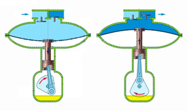
When the volume of the chamber increases, the compressor ‘sucks’ the air in. The suction valve opens only when the atmospheric pressure produces the effort big enough to overcome the spring of the valve.
Upon reaching the extreme lower position, the membrane begins to reverse, which results in compression of the air in the cylinder. The high-pressure air opens the discharge valve, after which the compressed air enters the discharge nozzle. The time interval from the opening to the closing of the injection valve corresponds to the injection phase.
Membrane compressors of this design are designed for compressing small volumes of gas to a small pressure — the final pressure depends to some extent on the material of the membrane, usually it does not exceed 2 Bars.
The membrane must withstand a large number of load cycles. It is most often made of rubber, rubberized fabric or silicone. During the production of compressors, membranes are subject to strict requirements regarding density and the absence of mechanical damage; multilayer membranes are made to increase the service life and improve tightness.
The main advantage of membrane compressors is that they are sealed, they have very small leakage relative to other types of volumetric machines.
Their disadvantage is rapid wear of the membrane. Besides, compressed air comes in pulses, not a continuous flow.
Membrane compressors are used in industries where the technological process involves working with toxic or inert gases.
The test stand that you are operating with has two opposite membrane chambers. The figures illustrate the kinematic diagram
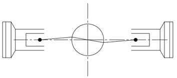
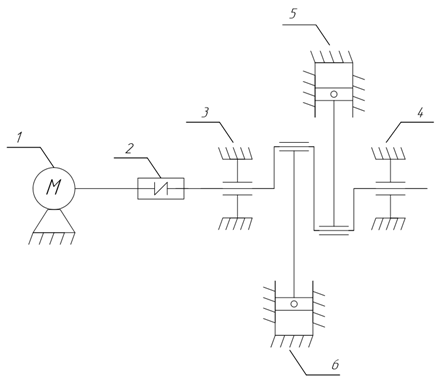
The mechanism of the membrane compressor is a crank-and-rod mechanism, driven by a drive motor 1.
The actuator is a single-stage membrane compressor with horizontal placement of membrane blocks. Such a design provides balancing inertial forces and reduction of the compressor’s size.
Learn more: Physics of a compressor machine
It is convenient to analyze the operating cycle of the compressor using the indicator diagram in \(P-V\) coordinates — the dependence of pressure on the volume of the chamber during the compressor cycle. The diagram is closed, its area is proportional to the work done.
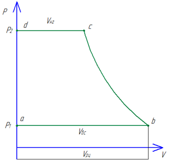
Indicator diagram of the working cycle of an ideal compressor.
At point a , the suction valve opens. The absorption process \(a - b\) begins with the position of the membrane at the top dead center (TDC) and ends when the membrane reaches the bottom dead center (TDC). During this period of time, the pressure remains unchanged, and the gas moves from the cavity of the suction pipe to the working chamber; the volume filled in this period of time is called suction volume \(V_{BC}\). For an ideal compressor, the suction volume is equal to the volume of the working cavity.
At point \(b\), the suction valve closes. The segment \(b - c\) corresponds to the compression process, during which the pressure in the working cavity increases from the suction \(P_1\) pressure to the discharge pressure \(P_2\), and the gas volume of the working cavity \(V_{BC}\) is compressed to the discharge volume \(V_{НГ}\).
At point \(c\), the discharge valve opens. Segment \(c - d\) corresponds to the injection process, which takes place under constant pressure. The gas, compressed to the injection volume \(V_{НГ}\), enters the injection nozzle. At point \(d\), the injection valve closes and the injection process is completed.
If we take into account that in an ideal compressor there is no harmful space (" dead " volume), then the indicator diagram is adjacent to the y-axis. On the segment \(d - a\) the pressure drops instantaneously from discharge pressure to suction pressure. The work cycle is ending.
The indicator diagram of a real compressor is shown in the figure below.
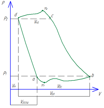
Indicator diagram of the working cycle of a real compressor.
The working cycle of a real compressor has significant differences caused by the presence of harmful space, changes in gas macro-parameters (temperature, pressure, volume) due to energy expenditure to overcome the hydraulic resistance of the gas flow in the suction and discharge lines, as well as non-constant heat exchange between the gas and the surfaces of the working chamber.
Point d stands back from the ordinate axis by the amount of the "dead" volume \(V_M\). " Dead " volume is the volume of gas at the position of the membrane at TDC, that is, the volume that the compressor is unable to displace from the working cavity. Physically, it consists of the volume of gas remaining after the injection process in the valve cavities and the volume limited by the compressor membrane and cover.
With the reverse movement of the membrane, the process of reverse gas expansion of the dead volume begins. On the indicator diagram, the process is represented by the section d - a , the time interval between the closing of the discharge valve at point d and opening the suction valve at point a . Gas expansion occurs until the pressure in the working chamber drops to the suction pressure \(P_1\). The flow of the process is characterized by the volume of expansion, by the amount of which the point a stands back from the ordinate axis. From the indicator diagram, it can be seen that the suction volume decreases by the amount of the expansion volume:
\[ V_{ВС} =V_{РО}+V_{М}-V_{РОЗШ}\]
where \(V_{ВС}\) is the suction volume, \(V_{РЦ}\) is the working volume of the cylinder, \(V_{М}\) is the "dead" volume, \(V_{РОЗШ}\) is the expansion volume.
Thus, the absorption phase does not begin at the beginning of the return stroke of the membrane, but at the end of the expansion process at the point a . In general, the absorption process takes place under variable pressure, mass and temperature of the gas. At the beginning of valve opening, the pressure drops to the minimum point \(M_1\). In order to fully open the valves, it is necessary to overcome hydraulic resistances, this leads to the fact that the actual pressure is less than the suction pressure \(P_1\). Pressure fluctuations are caused by variable membrane speed, valve movement dynamics, and pressure fluctuations in the suction line. The increase in temperature is due to the introduction of heat from the hotter surfaces of the working cavity and the transformation of gas energy into heat when it passes through the suction valve. At a constant pressure and temperature increase, the density of the working gas decreases, which negatively affects the mass productivity of the compressor .
The process of compression b - c proceeds with a variable mass of gas and a further increase in temperature. Unlike an ideal compressor, the curve b - c is a polytrope with variable exponent. This is caused by the heat exchange between the gas and the surfaces of the working cavity : at the beginning of compression, heat is supplied to the gas, and at the end , it is removed to the surfaces of the compression chamber.
Injection phase c - d is characterized by a higher pressure than the injection pressure \(P_2\), this is explained by overcoming the hydraulic resistance to fully open the valves. The maximum point \(M_2\) is observed at the moment of valve opening. Further pressure fluctuations are explained similarly to the suction phase a - b. The mass and temperature of the working gas decrease during the injection process.
Thus, compared to the ideal model, the real compressor is characterized by lower performance, additional power losses, as well as higher power consumption and stricter requirements for cooling means.
The reservoir
The installation is a closed system, which is filled with air. The reservior consists of three tanks(E1, E2, E3), interconnected by the pipelines (P2 – P6). The total volume of tanks is 0.05 m3. All pipelines are equipped with valves ( V1 – V7). The working tank is E3 equipped with a manometer D1. There is no safety valve.
The tank E1 is connected by a pipeline P1 (discharge nozzles) to the compressor.
The suction valves located on the cover of the membrane blocks ensure the entry of atmospheric air into the working chamber of the compressor.
During the operation of the compressor, air is pumped into the system through the tank E1 or E2, creating E3 pressure in the working tank, so it is necessary to ensure that the corresponding slide valves (V2–V3–V6 or V4–V5–V6) were opened. When the compressor is turned off, the pressure in the CU system slowly decreases due to leaky connections. With the help of valves V1, V7, you can quickly reduce the pressure in the system to zero.
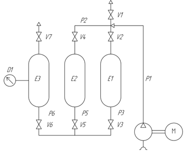
Pneumatic diagram of the compressor installation.
Technical parameters of the membrane compressor
| No | Parameter | Units of measurement |
Value | Conventional designation |
|---|---|---|---|---|
| 1 | Suction pressure | \(MPa\) | \(0.1\) | \(P_1\) |
| 2 | Injection pressure | \(MPa\) | \(0.2\) | \(P_2\) |
| 3 | Productivity | \(m^3/min\) | \(0.03\) | \(Q\) |
| 4 | Degree of pressure increase | — | \(2\) | \(\varepsilon\) |
| 5 | Receiver volume | \(m^3\) | \(0.005\) | \(V_p\) |
| 6 | Resistance torque | \(N \cdot m\) | \(1\) | \(M_c\) |