Theoretical part
Construction of the robot "Robot Arm":
The general appearance of the 6DoIt Mobile Robot Arm (6DMRA) is shown in Fig. 5. Its kinematic scheme is shown in Fig. 6.
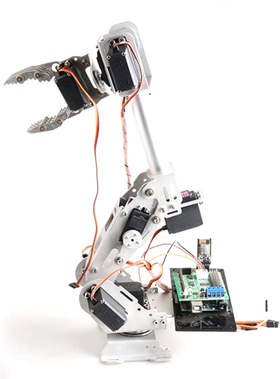
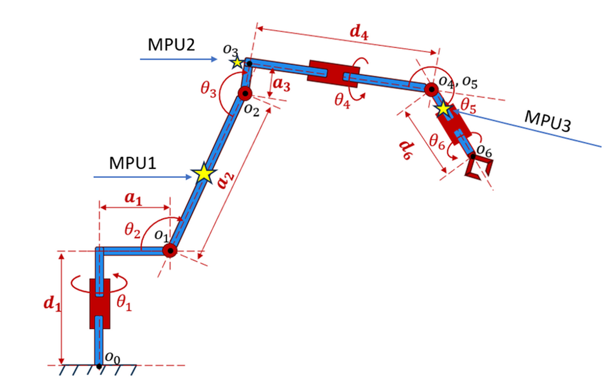
The 6DOF DoIt Mobile Robot Arm is a smaller version of industrial work with 6 degrees of freedom. This small manipulator weighing up to 1 kg with a maximum load of up to 0.5 kg can be mounted on a solid surface, installed on a table or on a special cabinet. The work base can be turned up to 180°.
The robot consists of six kinematic pairs. Each kinematic pair has its own geometric dimensions determined by parameters \(d_i\) and \(a_i\), and the angle of rotation of the movable link is \(θ_i\). Each axis of rotation is marked with the letter \(0_i\). The geometric dimensions of the manipulator are presented in Table 1.
| Axis | Connection angle (θі) | Link twisting (αі) | Link length (aі) (mm) | Link shift (dі) (mm) |
|---|---|---|---|---|
| 1 | θ1 | -90° | 45 | 75 |
| 2 | θ2 | 0° | 115 | 0 |
| 3 | θ1 | -90° | 20 | 0 |
| 4 | θ4 | 90° | 0 | 130 |
| 5 | θ5 | -90° | 0 | 0 |
| 6 | θ6 | 0° | 0 | 50 |
The working zone of the manipulator robot in the reference plane is determined by the inner and outer radius of the working surface. The inner radius of the working surface is 65 mm, the outer radius is 340 mm.
DENAVIT-HARTENBERG METHOD
Each kinematic joint (kinematic pair) of a 6DOF robot is rotational and has one degree of freedom of movement. The movement of the movable link of the articulation is determined by the so-called generalized coordinate - the angle of rotation \(θ_i\) (Fig.6).
When the manipulator moves in the working area of the robot, the generalized coordinates of each joint change, forming the grip movement trajectory. Having six manipulator joints, the 6DOF robot can adopt different geometric configurations of links at a given gripper positioning point. Therefore, it is important to be able to determine the absolute coordinates of the position of the links to control the geometric configuration of the manipulator in accordance with the given one.
The grip positioning point \(0_6\) is determined in the coordinate system \((x_0, y_0, z_0 )\), which is located at the point \(0_0\) of the beginning of coordinates (Fig. 6).
In the case when the absolute coordinates of the links are known, the grip position is determined uniquely in the \((x_0, y_0, z_0 )\)coordinate system. Thus, the direct problem of kinematics is solved: the calculation of the coordinates of the position and orientation of the coordinate system associated with the grip or working tool, with a given set of generalized coordinates of the manipulator. For this purpose, the Denavit-Hartenberg method is implemented, which has the following steps:
- Binding of coordinate systems to links of the manipulator.
- Determination of parameters of links and joints.
- Construction of homogeneous transformation matrices.
Binding of coordinate systems to manipulator joints. To bind coordinate systems to each joint, the following rules must be followed:
- Set the manipulator to zero (initial position).
- The \(z_i\) axis must coincide with the axis of rotation or the axis of translational motion \((i+1)\)st link.
- The \(x_i\) axis must be perpendicular to the \(z_{(i-1)}\) \((i-1)\)st link and cross this axis. The axis \(x_0\) is freely chosen.
- The \(y_i\) axis is the vector of multiplication \(\overrightarrow{y}_i=\overrightarrow{z}_i × \overrightarrow{x}_i\) and creates a right coordinate system.
Taking these rules into account for the DMRA robot, we have the following orientation of the joint coordinate systems (Fig. 7).
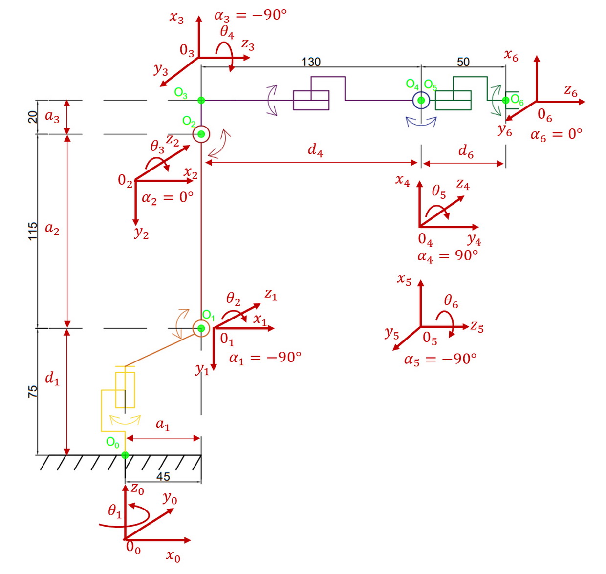
Determination of parameters of links and joints. The following Denavit-Hartenberg parameters are used for the links and articulations of the robot manipulator:
\(θ_i\) – the attached angle by which the \(x_{(i-1)}\) axis must be rotated around the \(z_{(i-1)}\)axis, so that it becomes co-directional with the \(x_i\) axis (the direction of rotation is determined by the right-hand rule);
\(d_i\) – the distance between the point of intersection of the \(z_{(i-1)}\) axis with the \(x_i\) axis and the beginning of the \((i-1)\)st coordinate system, measured along the \(z_{(i-1)}\) axis;
\(a_i\) – linear displacement - the distance between the intersection point of the axis \(z_{(i-1)}\) with the \(x_i\) axis and the beginning of the \((i)\)th coordinate system, calculated along the \(x_i\) axis, that is, the shortest distance between the axes \(z_{(i-1)}\) and \(z_i\);
\(α_{(i)}\) – angle displacement - the angle by which the \(z_{(i-1)}\) axis must be turned around the \(x_i\) axis, so that it becomes co-directional with the \(z_i\) axis (the direction of rotation is determined by the right-hand rule).
The \(a_i\) and \(α_i\) parameters are defined around the current (\x_i\) axis, and the (\d_i\) and \(θ_i\) parameters are defined around the previous \(z_{(i-1)}\) axis.
The parameters \(d_i\) and \(θ_i\) are always constant for all kinematic schemes and are determined by the design of the manipulators. As for the other parameters \(d_i\) and \(θ_i\), among them, only one parameter is constant, and the other is variable, depending on the type of articulation: in rotation motion the angle \(θ_i\) is variable, parameter \(d_i\) is consonant, and vice versa in translational motion.
The following algorithm is used to determine the Denavit-Hartenberg parameters:
- Rotation of the \((i-1)\)st system around the \(z_{(i-1)}\) axis clockwise (visually viewed from the point \(0_{(i-1)}\)) at an angle \(θ_i\) until the axis \(x_{(i-1)}\) becomes parallel and unidirectional to the axis \(x_i\).
- Shift of the rotated \((i-1)\)st system along the \(z_{(i-1)}\) axis by the dimension \(d_i\) to the alignment of the \(x_{(i-1)}\) axis with the \(x_i\) axis.
- The shift of system \((i-1)\)st along the \(x_i\) axis by the value \(a_i\) until the starting points of the coordinates of systems \((i-1)\) and \((i)\) do not coincide.
- Rotation of the \((i-1)\)st system around the \(x_i\) axis clockwise (when viewed from the point \(0_i\)) by an angle \(α_i\) until the \(z_{(i-1)}\) нaxis is aligned with the \(z_i\) axis.
As a result of the above algorithm, the parameters of the links and joints of the DMRA robot are as follows (Table 1).
Construction of uniform transformation matrices. Each homogeneous matrix of transformations (transfer matrix) matches the coordinates of the \(i-th\) link in the \(i-th\) coordinate system \((x_i, y_i, z_i)\) with respect to the coordinates of the coordinates of this link in the \(i-1\)st coordinate system \((x_{(i-1)}, y_{(i-1)}, z_{(i-1)})\)
| \begin{equation*} \left| \begin{array}{c} x_{i-1}\\ y_{i-1}\\ z_{i-1}\\ 1 \end{array} \right| = T_{i-1, i} \cdot \left| \begin{array}{c} x_{i}\\ y_{i}\\ z_{i}\\ 1 \end{array} \right|, \end{equation*} | (1) |
| \begin{equation*} T_{i-1, i} = \left| \begin{array}{cccc} c(θ_{i}) & -s(θ_{i})c(α_{i}) & s(θ_{i})s(α_{i}) & a_{i}c(θ_{i})\\ s(θ_{i}) & c(θ_{i})c(α_{i}) & -c(θ_{i})s(α_{i}) & a_{i}s(θ_{i})\\ 0 & s(α_{i}) & c(α_{i}) & d_i \\ 0 & 0 & 0 & 1 \end{array} \right|. \end{equation*} | (2) |
Taking into account Table 1 and formulas (1) and (2), we have the following transfer matrices for each articulation
| \begin{equation*} \left| \begin{array}{c} x_{0}\\ y_{0}\\ z_{0}\\ 1 \end{array} \right| = \left| \begin{array}{cccc} c(θ_{1}) & 0 & -s(θ_{1}) & a_{1}c(θ_{1})\\ s(θ_{1}) & 0 & c(θ_{1}) & a_{1}s(θ_{1})\\ 0 & 1 & 0 & d_1 \\ 0 & 0 & 0 & 1 \end{array} \right| \cdot \left| \begin{array}{c} x_{1}\\ y_{1}\\ z_{1}\\ 1 \end{array} \right|. \end{equation*} | (3) |
| \begin{equation*} \left| \begin{array}{c} x_{1}\\ y_{1}\\ z_{1}\\ 1 \end{array} \right| = \left| \begin{array}{cccc} c(θ_{2}) & -s(θ_{2}) & 0 & a_{2}c(θ_{2})\\ s(θ_{2}) & c(θ_{2}) & 0 & a_{2}s(θ_{2})\\ 0 & 0 & 1 & d_1 \\ 0 & 0 & 0 & 1 \end{array} \right| \cdot \left| \begin{array}{c} x_{2}\\ y_{2}\\ z_{2}\\ 1 \end{array} \right|, (рис.8), \end{equation*} | (4) |
| \begin{equation*} \left| \begin{array}{c} x_{2}\\ y_{2}\\ z_{2}\\ 1 \end{array} \right| = \left| \begin{array}{cccc} c(θ_{3}) & 0 & -s(θ_{3}) & a_{3}c(θ_{3})\\ s(θ_{3}) & 0 & c(θ_{3}) & a_{3}s(θ_{3})\\ 0 & -1 & 0 & 0 \\ 0 & 0 & 0 & 1 \end{array} \right| \cdot \left| \begin{array}{c} x_{3}\\ y_{3}\\ z_{3}\\ 1 \end{array} \right|, (рис.9), \end{equation*} | (5) |
| \begin{equation*} \left| \begin{array}{c} x_{4}\\ y_{4}\\ z_{4}\\ 1 \end{array} \right| = \left| \begin{array}{cccc} c(θ_{5}) & 0 & -s(θ_{5}) & 0\\ s(θ_{5}) & 0 & c(θ_{5}) & 0\\ 0 & -1 & 0 & 0 \\ 0 & 0 & 0 & 1 \end{array} \right| \cdot \left| \begin{array}{c} x_{5}\\ y_{5}\\ z_{5}\\ 1 \end{array} \right|, (рис.10), \end{equation*} | (6) |
| \begin{equation*} \left| \begin{array}{c} x_{5}\\ y_{5}\\ z_{5}\\ 1 \end{array} \right| = \left| \begin{array}{cccc} 1 & 0 & 0 & 0\\ 0 & 1 & 0 & 0\\ 0 & 0 & 1 & d_6 \\ 0 & 0 & 0 & 1 \end{array} \right| \cdot \left| \begin{array}{c} x_{6}\\ y_{6}\\ z_{6}\\ 1 \end{array} \right|. \end{equation*} | (7) |
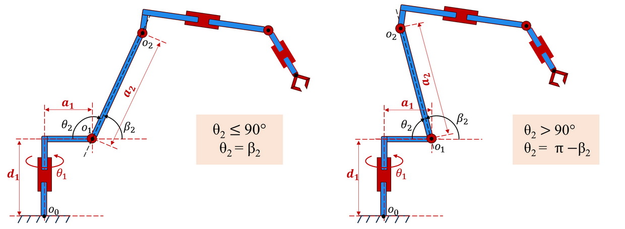
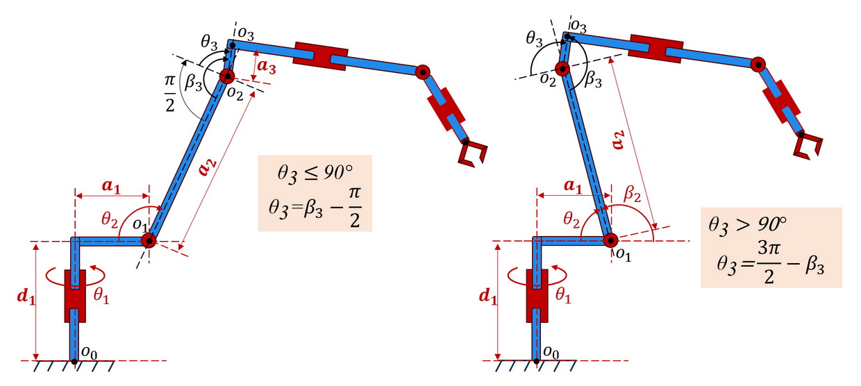
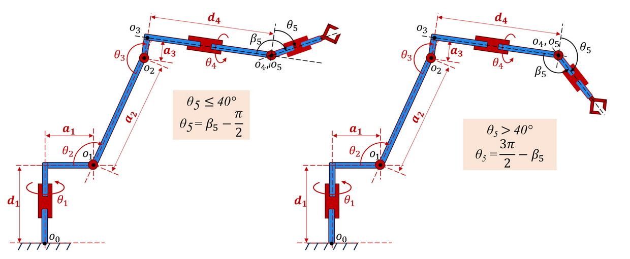
Using formulas (3)...(7), it is possible to obtain the coordinates of the \(i-th\) link of the manipulator \((x_{(0,i)}, y_{(0,i)}, z_{(0,i)})\) in the coordinate system \((x_0, y_0, z_0)\) if the coordinates of this link in the coordinate system \((x_i, y_i, z_i)\) and absolute coordinates of movements \(θ_i (i=0...i)\) of all links up to \(i-thї\).
| \begin{equation*} \left| \begin{array}{c} x_{0,1}\\ y_{0,1}\\ z_{0,1}\\ 1 \end{array} \right| = T_{0, i} \cdot \left| \begin{array}{c} x_{i}\\ y_{i}\\ z_{i}\\ 1 \end{array} \right| = T_{0, 1} \cdot T_{1, 2} \cdot \ldots T_{i-1, i} \cdot \left| \begin{array}{c} x_{i}\\ y_{i}\\ z_{i}\\ 1 \end{array} \right|. \end{equation*} | (8) |
Since the \((x_i, y_i, z_i)\) coordinate system is attached to the \(i-th\) joint of the manipulator, the coordinates of the moving link of this joint will be zero. Thus, having the transfer matrix \(T_{(0,i)}\) we can calculate the coordinates \((x_{(0,i)}, y_{(0,i)}, z_{(0,i)})\) of the \(i-th\) link of the manipulator in the \((x_0, y_0, z_0)\) coordinate system.

