Theoretical part
Calculation of the trajectory of Car Vali:
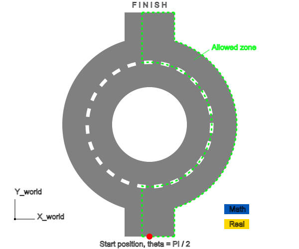
The robotic electric car "Car Vali" has to drive through the rotunda, fitting into the width of the Allowed zone of the road (Fig. 4). The start of the movement is defined in the coordinate system associated with the road (Fig. 4).
 Fig. 4. The route of the Car Vali electric robot»
Having tied this coordinate system to the front bridge of the robot at the beginning of the rotunda, we select the position in the coordinate system , which is rotated relative to the coordinate system, as the Start position by an angle (Fig.5).
 Fig. 5. Coordinate systems of the "Car Vali" robot-electric vehicle
To form a trajectory, it is necessary to enter trajectory sections of a given length at a certain angle step by step (Fig.5). To ensure that the robot moves at this angle, the angular speeds of rotation of the left and right wheels of the electric vehicle should be controlled, ensuring the difference in linear speeds of the wheels. , rpm, where – wheel radius. In this case, the linear speed of the electric vehicle (the speed of the point of the origin will be the average value of the linear speeds of the left and right wheels (Fig.5).
The robot rotates by an angle of with a shoulder (wheelbase width) relative to the axis of rotation passing through the corresponding wheel (Fig. 6).
 Fig.6. Turning of the "Car Vali" electric robot
Thus, we can write the following system of equations for the i-th section:
It follows from formula (4) that changes in the rotation angle at the -th step (section) added to the rotation angle at the -th step leads to the rotation angle .
Changing the angle of rotation leads to a change in coordinates in the coordinate system :
The position of the robot in the axes at the -th step will be determined by the coordinates


