Remote Control Experiment "CarVali"
Movement trajectory formation for the electric car robot "CarVali"
Motivation:
The purpose of creating the remote control laboratory stand "Car Vali" is to study the dynamics of a passenger car’s simplified model (electric car robot) movement in mechatronics tasks, with the possibility to observe transient processes in direct current motors (DCM).
The main task of the project is to implement remote control laboratory experiments using Web interface within the discipline "Mechatronic Complexes and Systems" for 5th and 6th-year students. This stand is part of the already existing laboratory stands with remote access, which were created within the Laboratories Across Borders (LAB) project in collaboration between Reutlingen University, Germany, and Dnipro University of Technology, Ukraine.

This experiment is dedicated to forming the movement trajectory of the electric car robot "CarVali", which has to pass through a roundabout, fitting into the width of the permissible zone (Allowed zone) of the road (Fig.1) using the control mechanisms implemented in the web interface of remote control.

Reference to the experiment page:
Methodological guidelines:
Structure of the stand
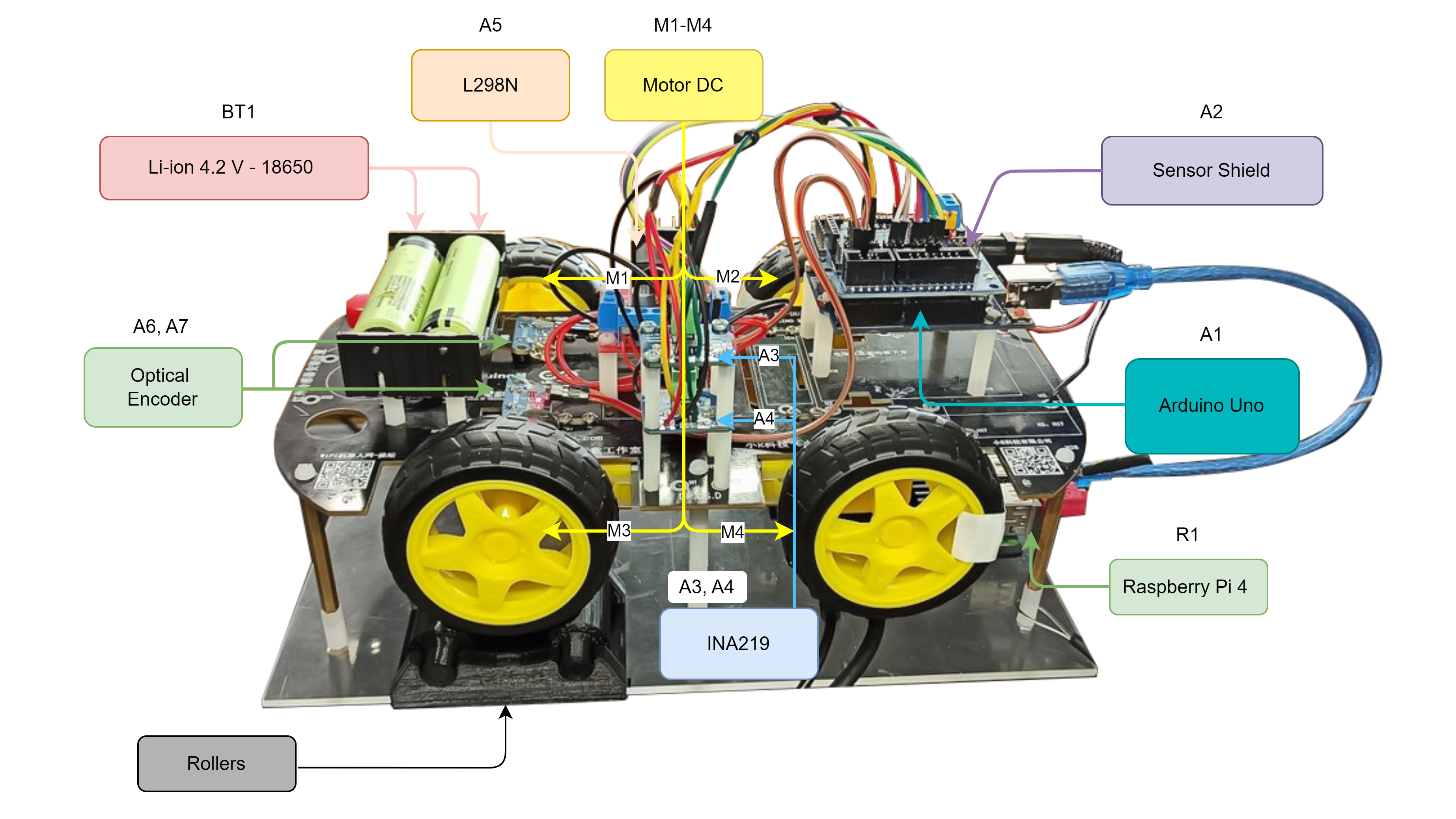
The laboratory setup of the electric car "Car Vali" is presented in Fig. 2. It consists of separate elements, the composition and details of which are provided below.

The stand consists of the following components:
А1 – The control system of the "Car Vali" stand is based on an Arduino Uno controller.
А2 – The expansion board, Sensor Shield V5.0, designed to simplify the connection of various sensors and modules to the Arduino Uno platform by expanding, duplicating, or arranging its inputs/outputs.
А3, А4 – The INA219 sensor module for measuring voltage and current in the power supply circuit of the DCM with high precision.
А5 – The dual-channel motor driver L298N is an electronic device that uses the H-bridge L298N to control DCMs. The main purpose of this module is to control the voltage and direction of the motors' rotation using PWM (Pulse Width Modulation).
A6-A7 – The optical encoder module, which, in combination with the supplied wheel with holes, serves to measure the number of "Car Vali" wheels rotations.
BT1 – The power source, which consists of two 18650 Li-ion batteries connected in series.
M1-M4 – Direct current motors EMC TT motor with a 1:48 gear ratio (dual-axis).
Rollers – plastic support with rollers that simulates the conditions of testing on a dynamometric stand.
R1 – Raspberry Pi 4, which acts as a server and communicates via the COM port with the control system of the stand - Arduino Uno.
Operating principle of the control system:
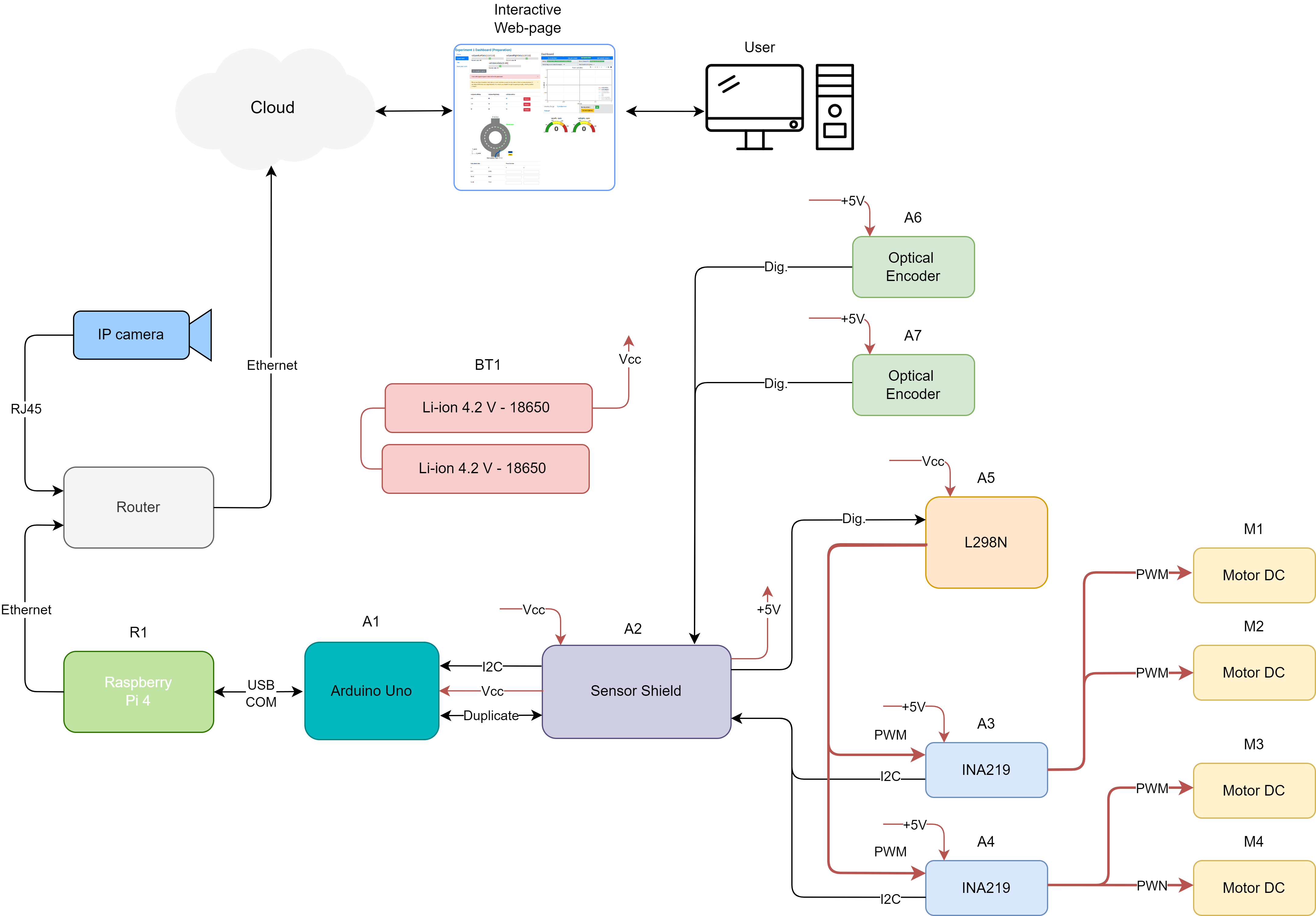
The operating principle of the control system for the setup will be considered using its functional diagram (Fig. 3).

The formation of the control signal on the "Car Vali" stand occurs by setting the appropriate parameters via a remote web interface. This interface is implemented on the basis of the Raspberry Pi 4 (R1) platform, which acts as a server. The interface is a web page that can be accessed remotely using a PC, tablet, or smartphone with most modern web browsers. The control effect, in the form of a data packet, is transmitted from Raspberry Pi 4 (R1) to the control system of the stand, based on the Arduino Uno platform (A1), via the COM port by connecting via USB-Type B. After processing the received data packet, Arduino Uno (A1) generates a task for the speed of rotation of the direct current motors M1-M4. From the Sensor Shield expansion board (A2) installed on Arduino Uno (A1), the signal is transmitted to the dual-channel motor driver L298N (A5). This driver changes the speed of rotation of two pairs of motors on each of its channels (Channel "A" - M1-M2, Channel "B" - M2-M3) by changing the supply voltage of the motors using PWM to execute the received task. The power supply for all components of the scheme (power and informational) is provided by Li-ion batteries (BT1).
INA219 sensors (A3-A4) are connected to each of the L298N (A5) channels for the purpose of measuring their current and voltage. The measurement of the rotation speed of motors M1 and M3 is carried out using optical encoders (A6-A7). This solution allows measuring the rotation speed of the drive on the right (M1-M2) and left (M3-M4) sides of "Car Vali" and have readings of current and voltage on each of them. The data obtained from the mentioned sensors are read in real-time by Arduino Uno (A1). After that, the collected data are formed into a data packet that is transmitted to Raspberry Pi 4 in the reverse direction. The received data stream is displayed on the web page using graph viewing tools.
The progress of the laboratory work can be monitored in real time through an IP camera that is installed on the "Car Vali" structure.

